Why AI Chrome Product Renders Look Warped—and How to Fix Reflections
A chrome product concept can look convincing at a glance while its reflections make a straight body appear dented or change shape between images. This guide shows industrial designers how to plan studio highlights, prompt a reference-guided render, and check the result against approved geometry.
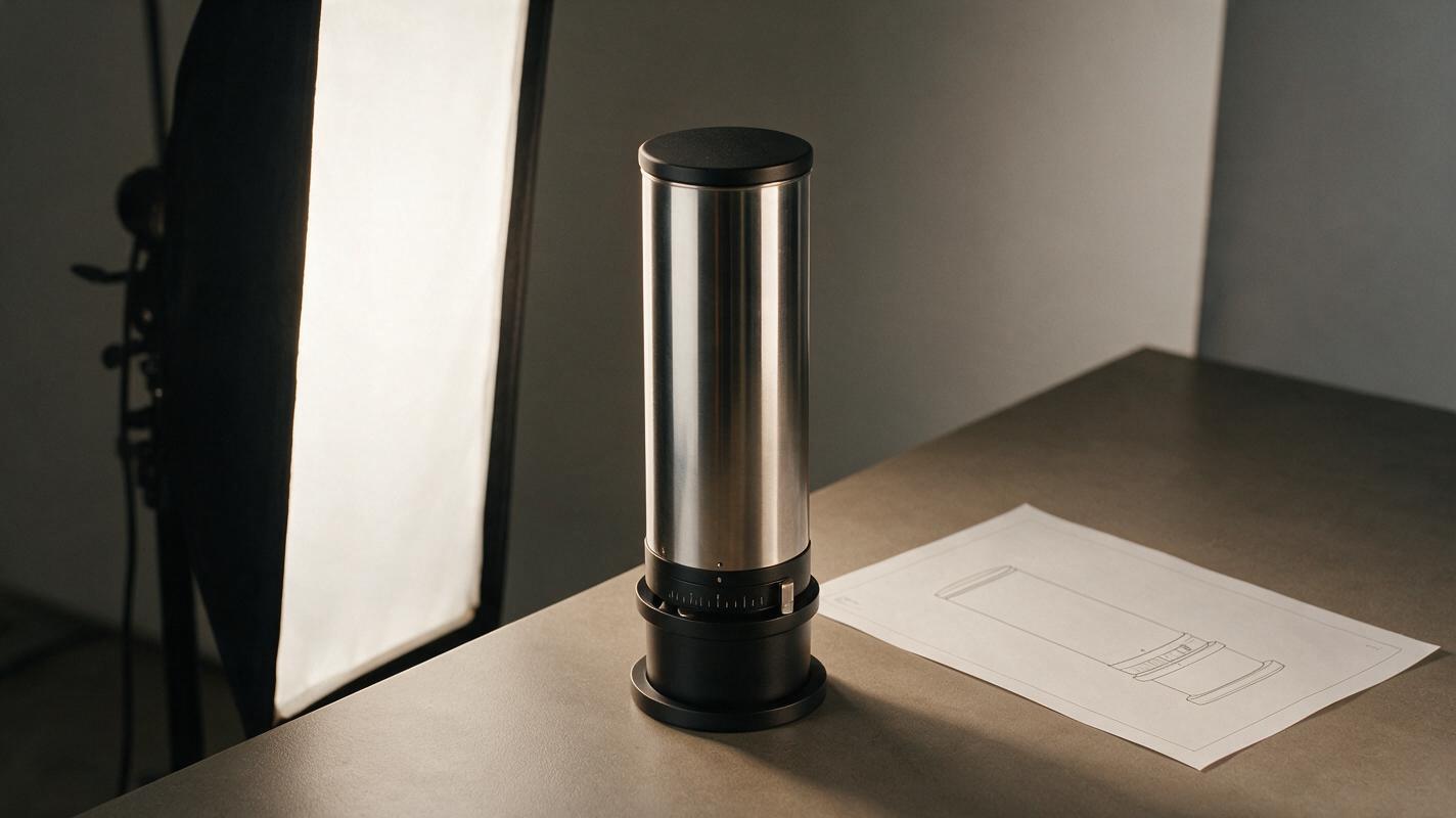
Table of contents
When the highlight redraws the product
A polished product render can fail even when its silhouette is intact. A broken vertical reflection may make a cylindrical housing look pinched; a bright patch crossing a seam can suggest a dent that is not in the design. If you are presenting a chrome or polished-steel concept, the goal is not simply more shine. It is a readable surface whose reflections support the approved form.
The example here is a cylindrical manual coffee-grinder concept with a polished metal body and matte black lid. The same checks apply to reflective lamps, audio products, small appliances, and hardware enclosures. Use AI imagery to explore presentation lighting, then verify anything that could be mistaken for a design feature against your source drawing or CAD model.
What a useful reflection should show
Chrome reflects its surroundings rather than displaying a fixed material color. In a studio image, broad light panels and darker flags can create long, controlled bands across a curved body. Those bands help a viewer understand the curvature—but only if they follow it coherently.
| What you see | Likely presentation problem | What to change |
|---|---|---|
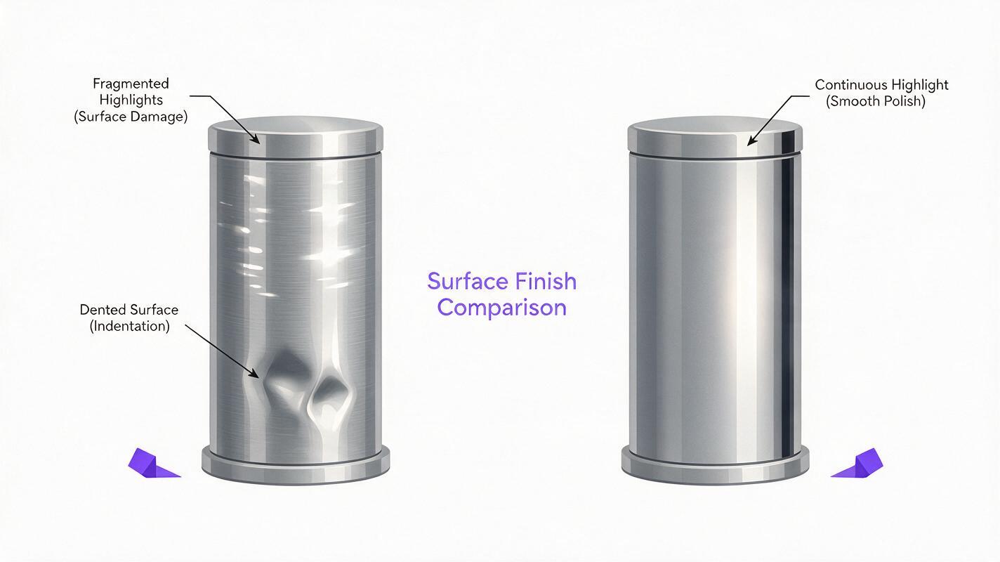
| Several short, disconnected white streaks | The lighting reads as random surface damage | Ask for one broad, continuous vertical softbox reflection |
| A bright band that bends sharply at an unbroken wall | The cylinder appears dented or pinched | Compare with the source silhouette; regenerate or replace the affected region |
| A mirror finish with no dark areas | The surface loses curvature and edge definition | Add a narrow dark flag reflection beside the main highlight |
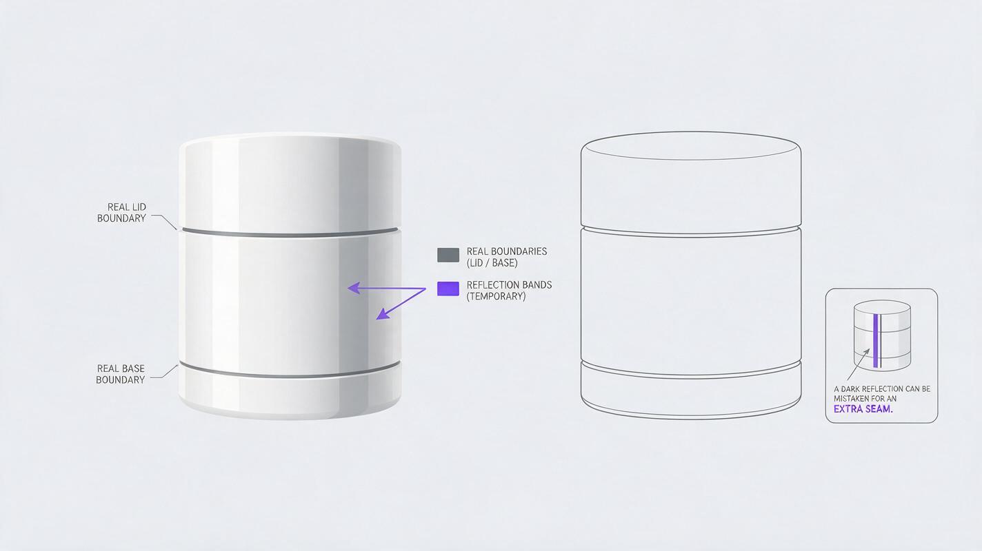
| A dark line that looks like an extra joint | A reflected flag resembles invented geometry | Move or soften the flag; check it does not terminate like a physical seam |
These are visual diagnostics, not a claim that a generated image is an optically accurate simulation. For a finish approval or engineering decision, inspect the actual material and use a controlled physical or CAD-based render.
Give the model a design it must not reinterpret
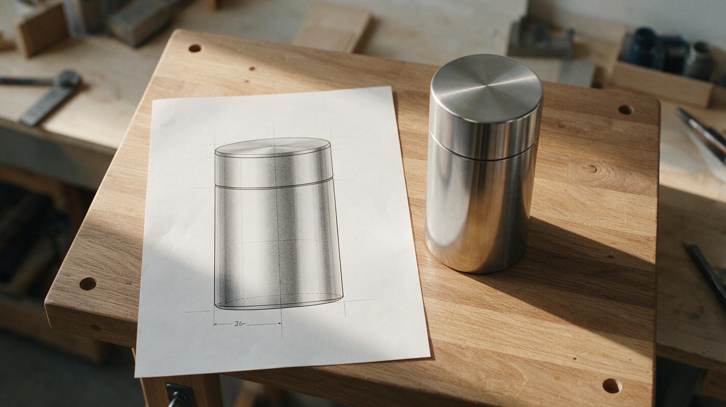
Start with the clearest approved view you have: preferably a CAD render or clean concept image at the intended camera angle. Include a second view only if it clarifies an ambiguous feature. For the grinder, mark the lid boundary, body diameter, base radius, and position of any real controls before generating presentation variants. A blurred or heavily stylized reference gives the model room to invent structure.
Use Nano Banana Pro for a reference-guided image attempt when that input workflow is available. If you are starting from a written concept rather than an approved image, text to image can explore lighting directions, but those outputs should not be treated as faithful renderings of a finalized design.
Keep the design brief separate from the lighting brief. “Polished metal body” describes a finish. “One broad vertical reflection on the camera-left side” describes an image-making decision. Neither instruction should authorize a new button, seam, taper, or logo.
Prompt for a legible polished surface
Specify the product, approved geometry, camera, reflective environment, and exclusions in plain language. Avoid piling on words such as “ultra glossy,” “luxury,” and “cinematic”; they do little to control where a reflection appears. This prompt assumes you have supplied the approved grinder image as a reference:
Make a studio presentation image of the supplied manual coffee-grinder concept. Preserve the reference silhouette, body diameter, lid height, base radius, visible part boundaries, and camera angle. The main body is polished stainless steel; the lid is matte black. Place the product against a quiet warm-gray studio background. Light the metal as though a large vertical softbox stands camera-left: show one broad, continuous highlight following the cylindrical curvature. Add a restrained darker vertical reflection camera-right to define the opposite edge. Keep both reflections on the surface; do not turn them into grooves or seams. Preserve the existing design features exactly. No added buttons, labels, openings, handles, dents, or changes in proportion.Generate a small set, then compare every candidate with the same approved view. Choose the image with the clearest geometry, not necessarily the most dramatic shine. If the tool offers local editing, isolate a defective reflection and request a lighting-only correction. If it does not, regenerate the whole image with a more specific description of the troublesome band.
Separate lighting artifacts from real design features
Reflective products make review unusually difficult: a dark vertical flag can look like a molded channel, while a softbox edge can resemble a second lid seam. Check the source and generated image side by side at both thumbnail size and full resolution. At thumbnail size, ask whether the overall cylinder reads correctly. At full resolution, trace the outer contour, lid line, base edge, and every purported opening.
A simple markup pass helps. Draw one color over approved physical edges and another over light and dark reflections. If a generated line starts or stops at a point where a real part would join, a viewer may interpret it as hardware. Adjust the lighting rather than explaining the ambiguity in a caption.
When you need multiple views, do not ask the model to infer an unseen back or side from one hero image. Supply an approved view for each camera angle, then apply a consistent lighting description to each. Match highlight width and background tone across the set, but allow reflections to shift with the camera; identical painted-on streaks across different views will look less credible.
Know when to stop prompting
If repeated generations keep bending the housing or altering a critical part line, take the approved CAD or product render as the final source of geometry. Use AI for a background or lighting reference, then finish the product image in a conventional rendering or compositing workflow. A polished concept image is successful only when the intended design remains easier to understand—not harder.
For an early presentation, you can test this prompt yourself with a non-confidential reference and review the results against your design drawing. Keep the original source beside every candidate while selecting. A plausible reflection is useful; an invented feature is not.
Final checklist
- Use an approved view at the intended camera angle as the geometry reference.
- Request a small number of broad, coherent light and dark reflections.
- Check that bright and dark bands do not read as dents, grooves, or extra seams.
- Compare silhouette and part boundaries with the source at full resolution.
- Use CAD or a controlled render when geometry or finish accuracy must be verified.
Keywords
ai product rendering, chrome product render, product visualization, industrial design ai, studio reflections, product design prompts