AI Exploded-View Product Renders Without Invented Parts
An AI-generated exploded view can make a product concept easier to discuss, but it can also invent fasteners, internals, and assembly relationships. This guide shows product designers how to build a presentation view from an approved parts list, control what the image implies, and review the result before sharing it.
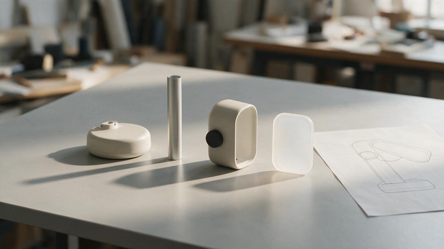
Table of contents
An exploded view should clarify a concept, not invent its construction
An exploded product render can look authoritative even when its screws, seams, and internal components came entirely from an image model. If you need a presentation image for a design review, begin with the parts you can actually identify, then treat everything else as unknown. The aim is to show the relationship between approved visible components—not to let a plausible-looking image become an accidental assembly specification.
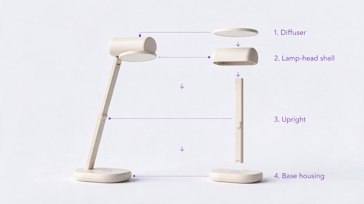
Consider a portable desk-light concept with an approved base housing, upright, lamp-head shell, and diffuser. Those four elements are enough to make a useful separated view. There is no reason for the render to add a battery pack, wiring path, hinge pin, or fastener pattern simply because those details would make it look more technical.
Define the parts that are allowed to separate
Before generating an image, make a small visible-parts inventory. For each element, record its source, appearance, and permitted position in the presentation view. If you only have one exterior sketch, do not treat an inferred rear surface or hidden mating feature as approved geometry.
| Element | What the reference establishes | What the render may show |
|---|---|---|
| Base housing | Exterior silhouette and finish | The same housing, displaced along the chosen view axis |
| Upright | Visible profile and relative length | Its visible form, without a newly invented connector |
| Lamp-head shell | Exterior shape and orientation | The shell as an identified presentation element |
| Diffuser | Visible outline and color | A separated face layer, without implied optical construction |
If the reference does not establish that two visible shapes are separate physical parts, label them as visual elements rather than components. That distinction matters when the image reaches engineering or manufacturing colleagues.
Useful rule: If you cannot point to an approved source for an exposed feature, do not let the exploded view present it as a fact.
Build a readable separation axis
A good concept view lets someone trace each displaced element back to its position on the intact product. Start with an approved assembled view and choose a camera angle that makes the major silhouettes legible. Keep that camera, scale, and orientation consistent in the separated version. Move elements only far enough apart to distinguish them; excessive spacing makes their relationships ambiguous.
For the desk light, the diffuser can sit just forward of the lamp-head shell, while the head, upright, and base remain aligned with their locations in the assembled image. Use thin alignment guides only if they help explain that relationship. Avoid arrows that imply an installation direction you have not established.
A simple companion graphic is often more trustworthy than a single dramatic render: place the approved assembled view beside the separated concept view at a matched scale. Reviewers can then spot a changed curve or a newly introduced seam immediately.
Generate a concept view without fabricating hardware
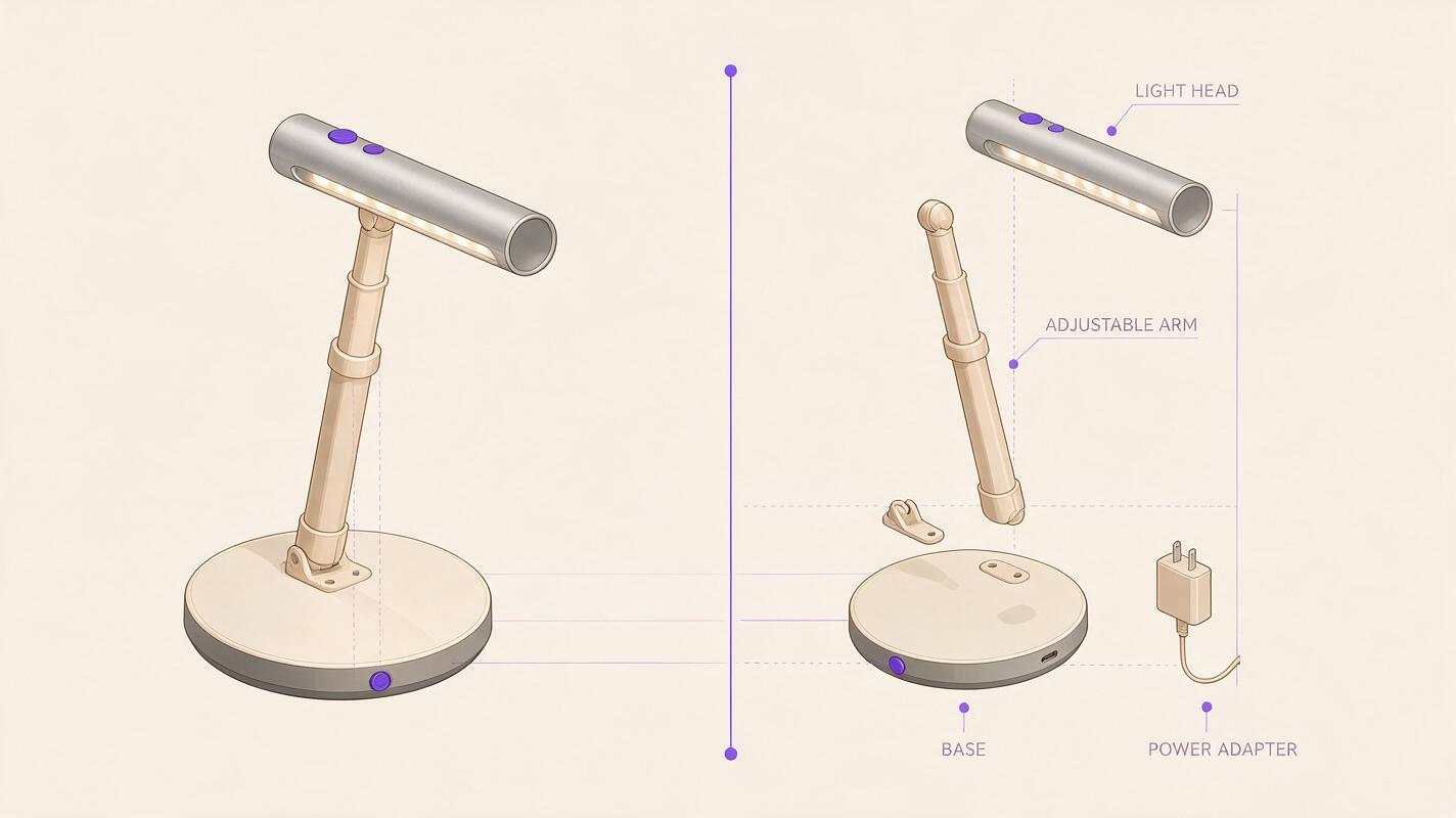
Use the assembled render or approved reference sheet as the image reference. Nano Banana Pro can be used to explore the presentation image; treat its output as a candidate to inspect, not as confirmation of the product’s construction. In MagicBoat’s ai image generator, keep the request focused on the four identified elements and their visual arrangement.
Create a clean editorial exploded-view concept image of the portable desk light in the supplied reference. Preserve the approved silhouette, proportions, colors, and camera angle. Show only these four identified visual elements: base housing, upright, lamp-head shell, and diffuser. Separate them slightly along clear, consistent axes so their positions relative to the assembled product remain obvious. Use a plain warm-gray studio background and soft lighting. Do not add screws, magnets, batteries, circuit boards, wiring, hinge mechanisms, hidden interfaces, labels, dimensions, or additional seams. This is a presentation concept, not an engineering assembly drawing.If the model keeps introducing mechanical detail, stop asking it to reveal a complete assembly. Generate a restrained background or presentation layout instead, then place individually approved part images into that layout. This gives you direct control over the parts and their spacing. It is also a better option when the exact exterior silhouette must survive unchanged.
For a prompt-only exploratory image, ask for a second version with less separation and no cutaway surfaces. Smaller changes often leave fewer opportunities for the model to invent unseen geometry.
Compare the output against the source
Inspect the image by element, not just by overall plausibility. A convincing render may still have moved a joint, thickened a diffuser, or turned one housing into two. Compare the assembled and separated views side by side, then mark each difference as approved, presentation-only, or unsupported.
- Count: Are there exactly the permitted elements, with no new rings, brackets, or internal modules?
- Shape: Does each visible silhouette match its reference, including edge radius and thickness?
- Placement: Can each displaced element be traced to its position on the intact product?
- Claims: Do shadows, arrows, labels, or exposed surfaces suggest an unverified mechanism?
Remove an unsupported detail rather than trying to explain it away in a caption. If removal changes the rest of the product, composite approved elements onto a simpler generated background. Keep the original reference accessible so reviewers can distinguish a design decision from image-model improvisation.
Label the result for its actual purpose
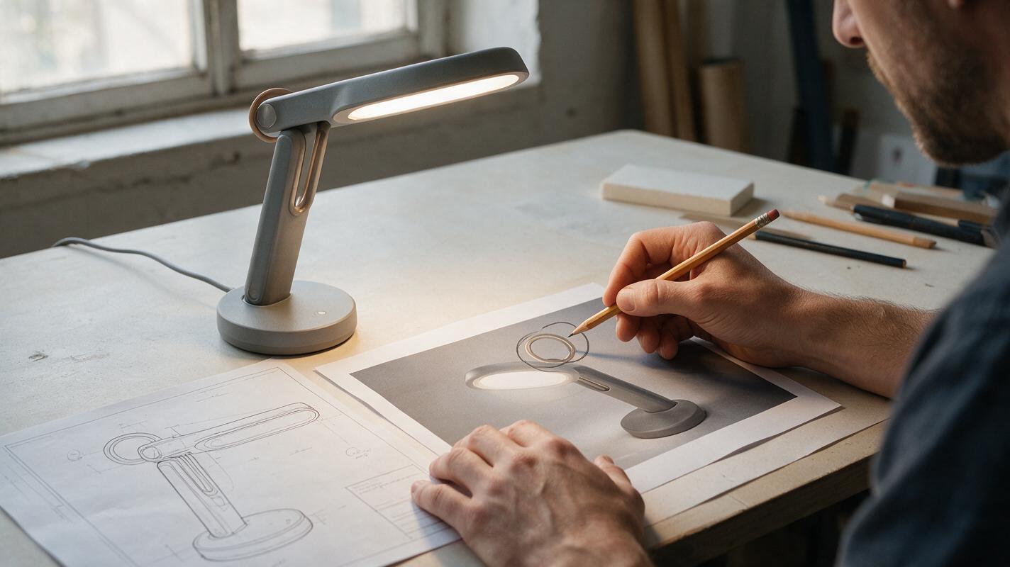
“Exploded view” can imply that the image describes a real assembly. If the product architecture is still open, a caption such as “Separated concept view—visual elements and spacing are illustrative” gives the image a more accurate role. Do not add part numbers, torque values, dimensions, or assembly instructions unless they come from an approved source.
This kind of image is most useful for discussing form, CMF boundaries, and which visible elements deserve further development. It is not evidence of fit, fastening, serviceability, optical performance, or manufacturability. When those questions become the purpose of the review, move to verified CAD geometry and an engineering-controlled drawing.
Final checklist
- List every element allowed in the separated view and identify its source.
- Keep the camera, scale, proportions, and finishes consistent with the approved product image.
- Reject invented internals, fasteners, mating features, and extra seams.
- Compare the separated image with the intact reference at a matched scale.
- Caption unverified spacing or construction as illustrative.
Have an approved product reference and parts inventory ready? test this prompt yourself, then check every generated element before putting the image in a design review.
Keywords
ai exploded view, product concept render, industrial design ai, product visualization, exploded view prompt, nano banana pro