Why AI Folding Product Renders Break at the Hinge—and How to Fix Them
AI-generated open and closed product renders can look convincing separately while depicting two different hinge designs. This guide shows how to use a fixed pivot, matched reference views, and a simple geometry check to present a folding concept without implying that its mechanism has been engineered.
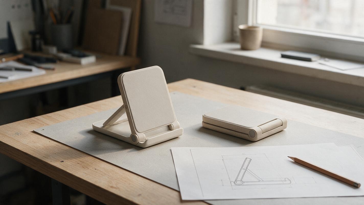
Table of contents
One product, two positions—not two different mechanisms
An open render and a closed render of a folding product should agree on more than color and silhouette. If the hinge moves between images, the panel changes thickness, or a hidden support appears only in the open view, the pair no longer explains the same concept. For a design review, that can be more misleading than an obviously rough sketch.
The practical fix is to define the product's rigid parts and pivot before asking AI to render either position. Use reference-guided image generation for presentation quality, but keep the underlying motion and geometry under designer control.
Why a plausible open view can still be wrong
An image model can depict a convincing folded stand without calculating how its parts rotate. When it receives separate prompts such as “open phone stand” and “closed phone stand,” it may solve each image independently. The results can inherit different panel proportions, hinge locations, or clearances.
For a folding desktop phone stand, watch for three particularly revealing errors:
- Pivot migration: The rotation axis sits near the rear edge when open but near the center when closed.
- Changing rigid parts: The panel becomes shorter, thinner, or differently rounded between states.
- Invented mechanism: A strut, detent, or second joint appears to make the open pose look stable.
Those are geometry errors, not lighting imperfections. A better prompt alone may reduce them, but an authoritative reference for each pose gives the model less to invent.
Build a two-state reference that defines the hinge
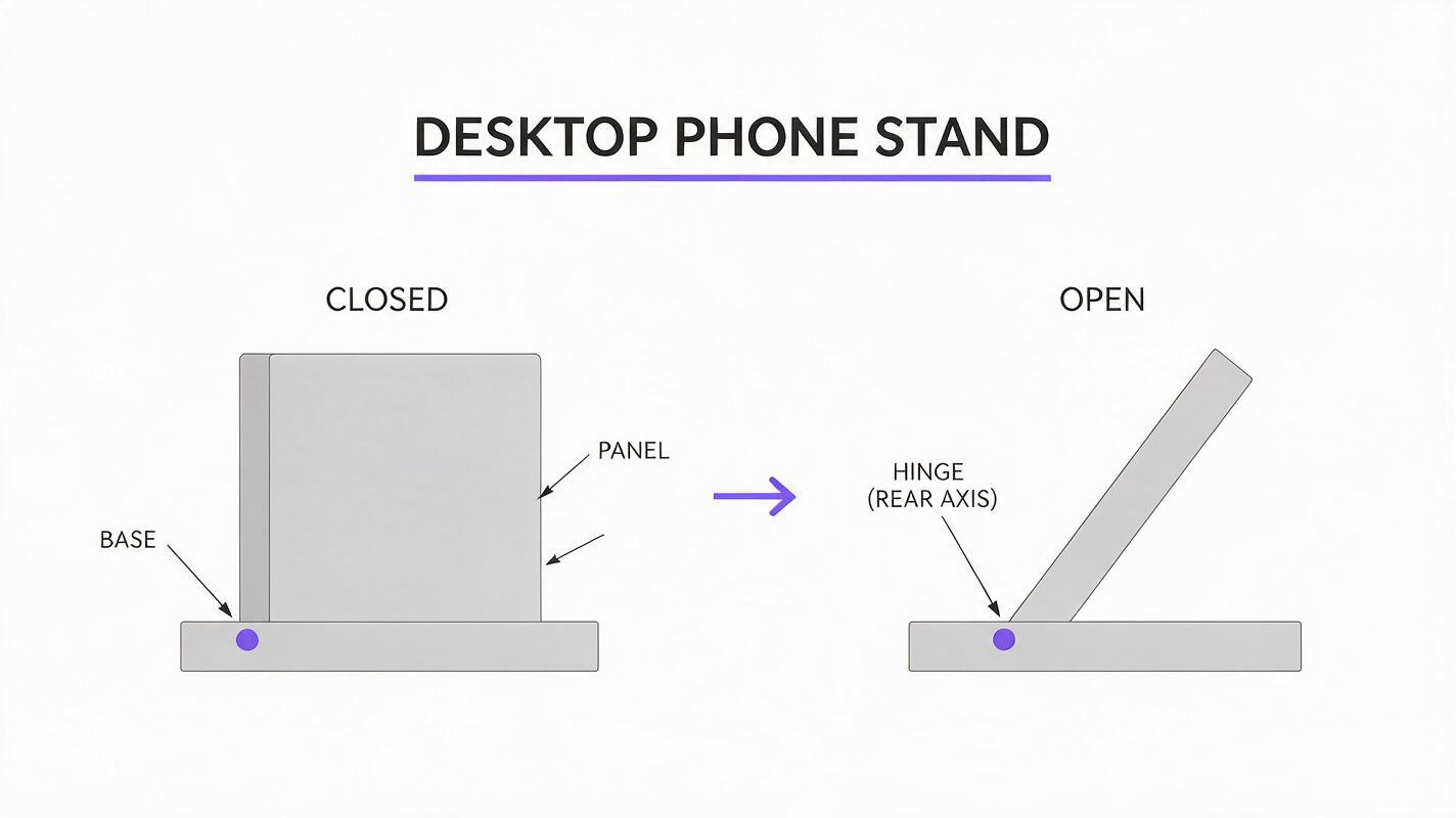
Start with a simple side elevation from CAD, a dimensioned drawing, or a carefully constructed vector sketch. This example uses a rectangular base and one rigid panel rotating around a single fixed axis at the rear of the base. Draw both states at the same scale, with the pivot marked at identical coordinates relative to the base.
For an illustrative brief, the base might be approximately 120 mm deep and 8 mm thick, with a 110 mm-long panel shown closed and raised to roughly 65° in the open state. These are concept inputs, not measurements established by an AI render. If you have actual CAD, use its dimensions and hinge center instead.
Keep the reference sheet deliberately plain: a closed side view, an open side view, and one approved three-quarter view if available. Label the parts outside the artwork rather than relying on the image model to draw precise annotations. Specify what remains rigid, where rotation occurs, and which side of the panel faces outward in each pose.
A reference sheet can define an intended pose. It cannot prove that a hinge clears adjacent parts, supports a load, or can be manufactured.
Render the states as a matched pair
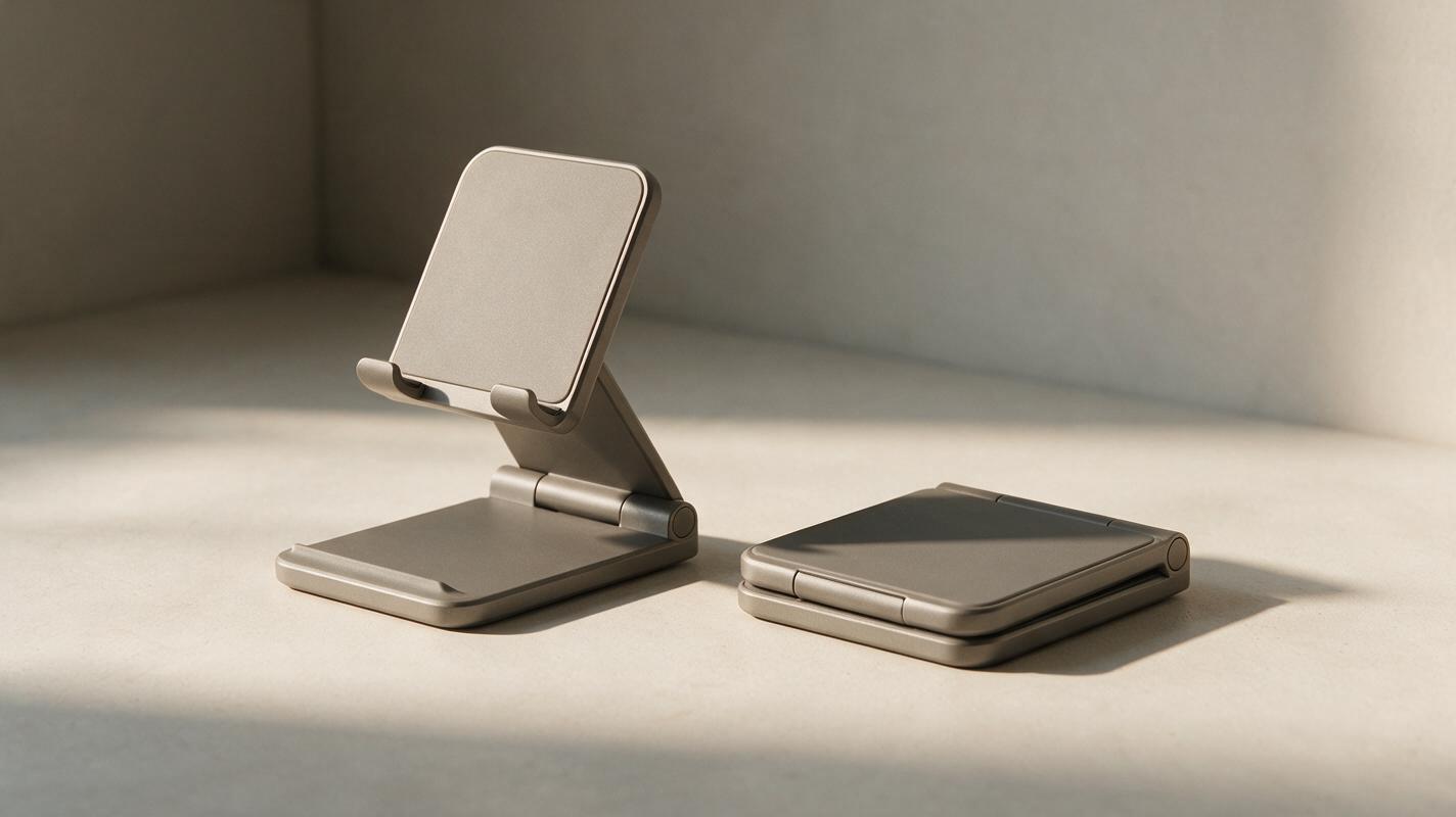
Use the same source sheet, product description, background, camera direction, and lighting for both requests. In nano banana pro, reference-guided image creation is most useful here as a presentation pass over already-defined poses—not as the source of the hinge design. Generate the open and closed states separately so each request has one unambiguous target.
Keep the camera near the reference viewpoint. A modest three-quarter angle can show material and thickness, but a dramatic change of viewpoint makes hinge discrepancies harder to catch. Ask for a neutral studio surface and restrained reflections; glossy highlights can conceal where one part ends and another begins.
Prompt for the open position
Using the attached two-state reference sheet, make a realistic concept presentation render of ONLY the open folding desktop phone stand. Preserve the base outline, panel length, panel thickness, edge radii, and the single hinge axis at the rear of the base. Show the panel in the raised pose indicated by the open side elevation. One rigid panel rotates around one fixed pivot; do not add struts, extra joints, buttons, cables, or feet. Match the reference's three-quarter camera direction. Matte warm-gray polymer, soft studio light, neutral background. No phone, text, dimensions, or engineering callouts.Prompt for the closed position
Using the SAME attached two-state reference sheet, make the matching closed-position render of the SAME folding desktop phone stand. Keep the base and panel identical to the open design: same outlines, thicknesses, edge radii, material, and single fixed hinge axis at the rear of the base. Show the panel rotated into the closed pose indicated by the closed side elevation; allow natural occlusion where parts overlap. Match the open render's camera direction, framing scale, studio light, and background. Do not add or remove components. No phone, text, dimensions, or engineering callouts.If the first results disagree, do not select the prettiest open image and then ask the model to “make it fold.” Return to the reference sheet. Clarify the pivot position or simplify the camera angle, then regenerate the mismatched state. A consistent pair is more useful than two individually polished images.
Check the pair where the hinge meets the housing
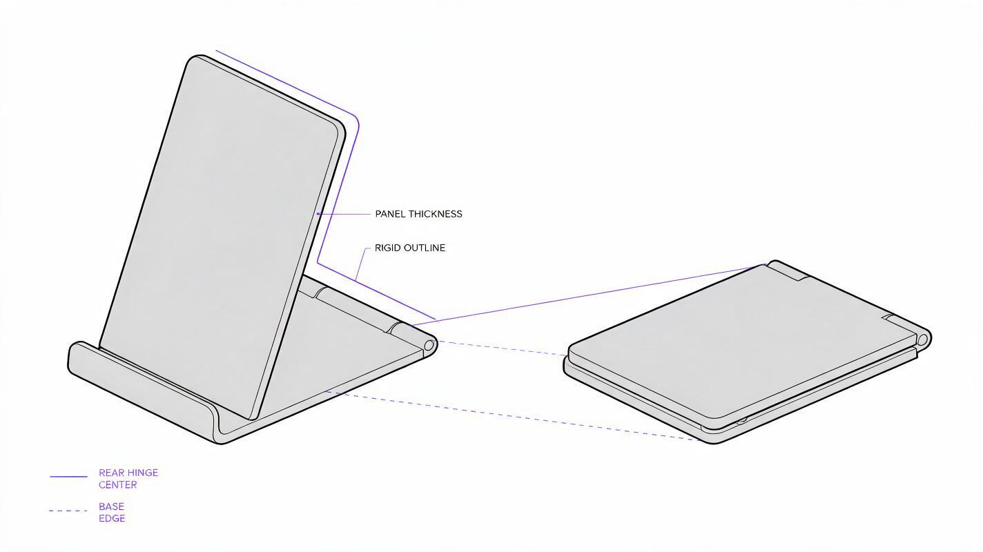
Place both renders beside the source elevations at a similar displayed scale. Compare identifiable rigid features rather than overall visual impression. The base's front and rear edges, panel end, hinge center, and panel thickness should remain recognizable across both images.
| Check | What should remain consistent | What a failure looks like |
|---|---|---|
| Pivot | Its location relative to the base's rear edge | A hinge that slides forward in one state |
| Panel | Length, thickness, corners, and surface orientation | A shorter or newly curved closed panel |
| Parts count | The same approved rigid components | An unexplained support arm or second joint |
| Occlusion | Surfaces hide according to the intended pose | Both sides of an overlapping panel visible at once |
For a tighter check, trace the base outline and hinge center over each image in a graphics editor. Align the bases, not the full product bounding boxes: an open product naturally occupies more vertical space. If the hinge centers cannot be aligned without distorting one image, the pair needs revision.
Do not use these images to approve clearance, stability, load capacity, or tooling. Check those questions in CAD, with a physical mockup, or through the team's normal engineering review. The renders communicate the intended design; they are not evidence that the mechanism works.
Present the movement without overstating it
A review slide can show the matched open and closed renders next to the simple side elevations. Label them “concept position: open” and “concept position: closed.” If intermediate motion matters, create its pose in CAD or drawing form first rather than asking an image model to infer the path between endpoints.
Keep the approved geometry visible in the presentation. A short caption such as “Single rear pivot; rotation and clearances pending mechanical validation” makes the design intent clear without turning a polished visualization into an unsupported engineering claim.
Final checklist
- Both poses come from the same parts list and fixed pivot location.
- Rigid dimensions, edge details, and materials remain consistent.
- Open and closed renders use comparable camera angles and lighting.
- No unapproved supports, joints, or functional claims appear.
- Mechanical clearance and stability are checked outside the AI images.
Once your two-state reference is ready, test this prompt yourself with the open pose first, then use the same sheet to make its matching closed render.
Keywords
ai product design, folding product render, hinge consistency, product visualization, industrial design ai, reference-based image editing