How to Make an AI Exploded View Without Inventing Product Parts
An exploded-view concept can communicate assembly and design intent, but image generation may add convincing parts that do not exist. This guide shows product designers how to build a presentation-ready view from a verified component list, controlled part positions, and AI-assisted finishing.
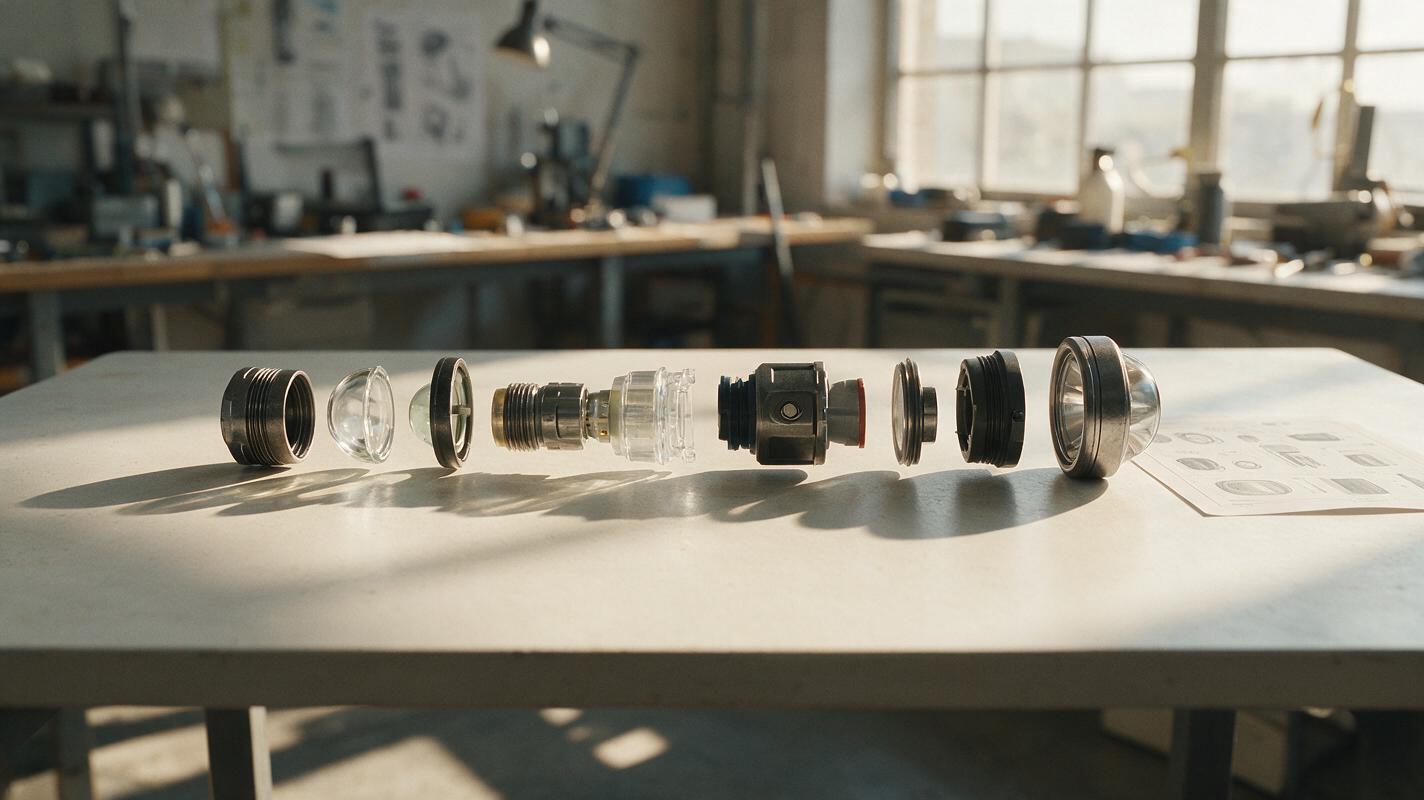
Table of contents
Make the assembly clearer, not more fictional
An AI-generated exploded view can look persuasive while quietly adding a circuit board, fasteners, or internal layers that were never in the design. For a product review, that is worse than an unfinished image: viewers may mistake invented detail for an engineering decision.
The safer approach is to control the parts and their positions first, then use AI to improve the presentation. This walkthrough uses a portable flashlight head and body as an example, but the method applies to small electronics, appliances, and other products with a defined component breakdown. The result is a concept presentation image, not an assembly instruction or proof of manufacturability.
Step 1 — Lock the component list before making an image
Start with a component list approved by the designer or hardware team. For the example flashlight, the visible exploded sequence might be front bezel, lens, reflector, LED board, heat sink, main barrel, battery cartridge, and rear cap. That is a presentation sequence, not a claim that every flashlight uses those components.
Give each item a stable name and decide whether it should appear as a separate visible piece. Record the approximate orientation, relative size, finish, and source reference for each part. If the battery cartridge is not designed yet, leave it out or label the view as a speculative concept. Do not ask a model to fill the gap.
| Check | Question to answer | Why it matters |
|---|---|---|
| Part count | Which distinct pieces are approved for display? | Prevents attractive but invented internals. |
| Order | Which part sits ahead of or behind each neighbor? | Keeps the visual sequence intelligible. |
| Source | Is each shape based on CAD, a drawing, or an approved concept? | Separates design evidence from visual interpretation. |
| Visibility | Are hidden details intentionally omitted? | Avoids presenting guesses as specifications. |
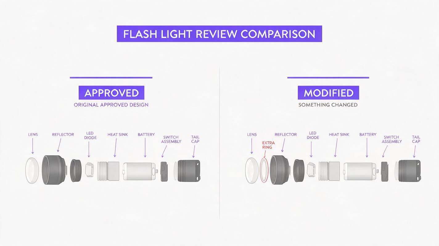
Review rule: If a teammate cannot point to a source for a depicted part, remove that part or mark the image clearly as speculative.
Step 2 — Establish the exploded geometry outside the prompt
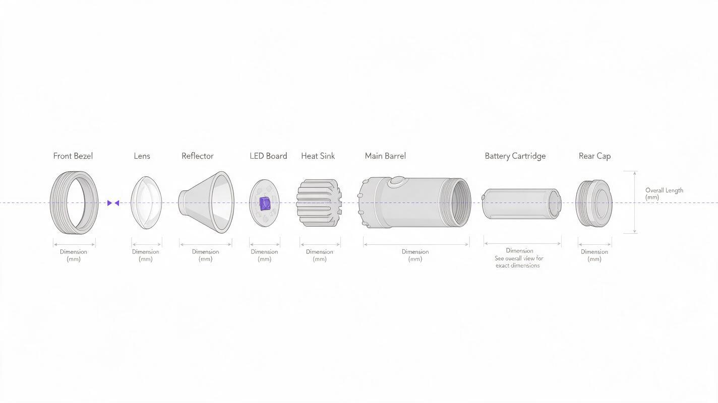
Use CAD exports, isolated render layers, or clean component cutouts when available. Arrange the pieces along a single axis in a layout tool before adding presentation effects. For the flashlight, align cylindrical components horizontally and leave enough space to see where one piece ends and the next begins. Keep their diameters consistent with the source; an exploded view changes position, not the physical size of a component.
A simple placement board is more reliable than asking a generator to infer assembly order from one product photo. Use a neutral background and place each component on its own layer. Put temporary identifiers beside the parts while checking the layout, then remove them for a clean hero image or replace them with deliberate callouts in your design software.
- Use one projection: Avoid mixing a side view of the barrel with a three-quarter view of the cap.
- Keep a shared centerline: Small intentional offsets can reveal hidden surfaces; random offsets suggest the parts do not fit.
- Leave generous gaps: Each part needs a readable silhouette, especially at thumbnail size.
- Reserve space for labels: Add final text separately rather than relying on generated lettering.
If no CAD exists, approved sketches can still provide the arrangement, but treat unseen surfaces as unresolved. A polished depiction should not imply they have been engineered.
Step 3 — Use AI for the scene, not for the bill of materials
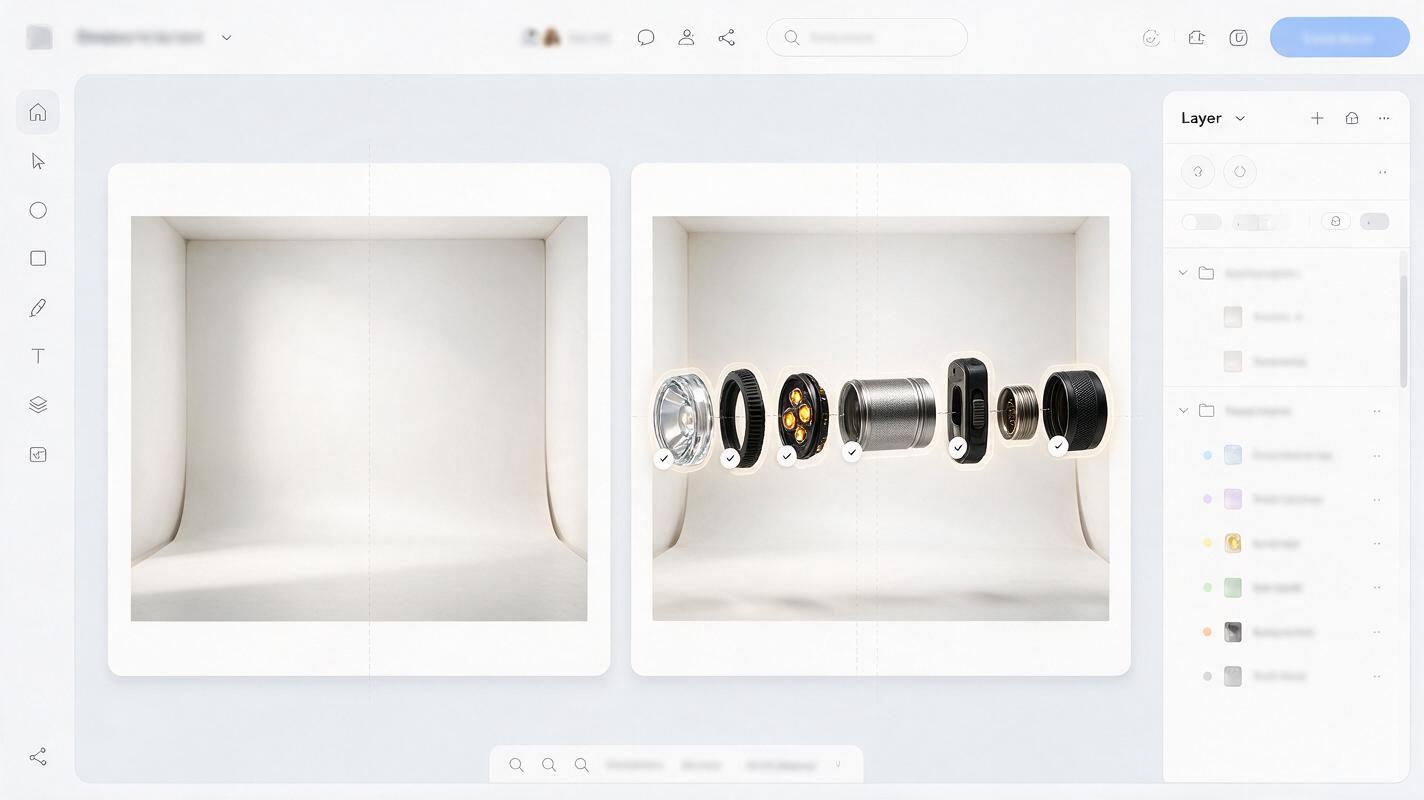
Once the parts are placed, decide what the model is allowed to change. A reference-capable image editor can be asked to refine lighting and backdrop around an existing composition. If that editor alters components despite the instruction, use its result only as a lighting reference and composite the verified parts back over it.
An alternative is to use an ai image generator to produce an empty product-photography stage—surface, shadows, and background—with no flashlight in it. Place your verified component cutouts onto that stage afterward. This keeps the generative task separate from component authorship.
Prompt for an empty presentation stage:
Minimal editorial product-photography set for a horizontally arranged
exploded-view image of a small handheld device. Warm off-white seamless
background, matte pale stone surface, soft daylight from upper left,
subtle contact-shadow area across the center, generous negative space
around all edges. No product, no components, no hardware, no labels,
no diagrams, no text, no logos.
For image editing, provide the arranged parts board as the reference and narrow the request:
Reference image: approved arrangement of eight flashlight components.
Keep every component's silhouette, count, relative scale, order,
orientation, spacing, and position unchanged. Adjust only lighting,
background tone, and realistic shadows. Do not add screws, wires,
connectors, labels, internal layers, or extra product parts.
If a component cannot be preserved, leave that area unchanged.
Use the prompts as constraints, not guarantees. Test this prompt yourself with a low-stakes draft, then compare the output against the approved board at full size before using it in a review.
Step 4 — Inspect the result like a component drawing
Visual plausibility is not the acceptance test. Put the generated version beside the approved arrangement and check each component from front to back. Count parts first, then inspect silhouette and alignment. Look for a doubled lens, a new threaded ring, a PCB with imaginary ports, or a cap whose opening has silently changed.
Pay special attention to transitions where a model may blend neighboring parts. The heat sink should remain a distinct component if it was distinct in the source. A convincing shared shadow must not hide a gap or make two pieces appear fused.
| Failure | Likely cause | Practical fix |
|---|---|---|
| Extra fasteners or circuitry | The model interpreted “technical” as permission to add detail. | Remove that language; edit the stage only or restore the source cutouts. |
| Parts change size | The model reimagined depth and perspective. | Keep the original components as fixed layers and adjust lighting separately. |
| Order becomes unclear | Gaps or shadows overlap adjacent pieces. | Increase spacing and soften shadows before another pass. |
| Generated labels are wrong | Text was produced as image content. | Remove it and add verified labels in the final layout. |
If the intended audience needs to evaluate fit, tolerances, serviceability, or manufacturing sequence, return to CAD or an engineering drawing. An AI-assisted exploded view is useful for communicating a concept; it cannot validate how the product assembles.
Step 5 — Deliver two views for a useful design review
Export a clean presentation image and a second, annotated review image. The clean version should make the product legible at a glance. The review version should number the verified parts and state the image's status—for example, “Concept exploded view; spacing exaggerated for clarity.” Add the component names in your layout software, where spelling and placement remain under your control.
Keep the approved arrangement board with the final file. When someone asks whether a visible ring or opening is intentional, you can trace it back to its source rather than debate what the generator appeared to invent. That source board also makes revisions faster: update the changed part without rebuilding the entire visual narrative.
Final checklist
- Every depicted component appears on the approved list.
- Part order, relative size, and orientation match the source arrangement.
- No generated fasteners, circuitry, openings, or materials are presented as facts.
- Labels are added and checked outside the generated image.
- The delivery identifies the view as conceptual when engineering details remain unresolved.
Keywords
ai exploded view, product exploded view, industrial design ai, product visualization, exploded view prompt, product presentation