Why AI Product Renders Put Cables in the Wrong Place
A convincing hardware render can still fail if its cable appears to enter the wrong surface, bends unnaturally, or hides an unresolved connector. This guide shows product designers how to define a visible cable path, edit an approved render, and check the result without treating the image as engineering proof.
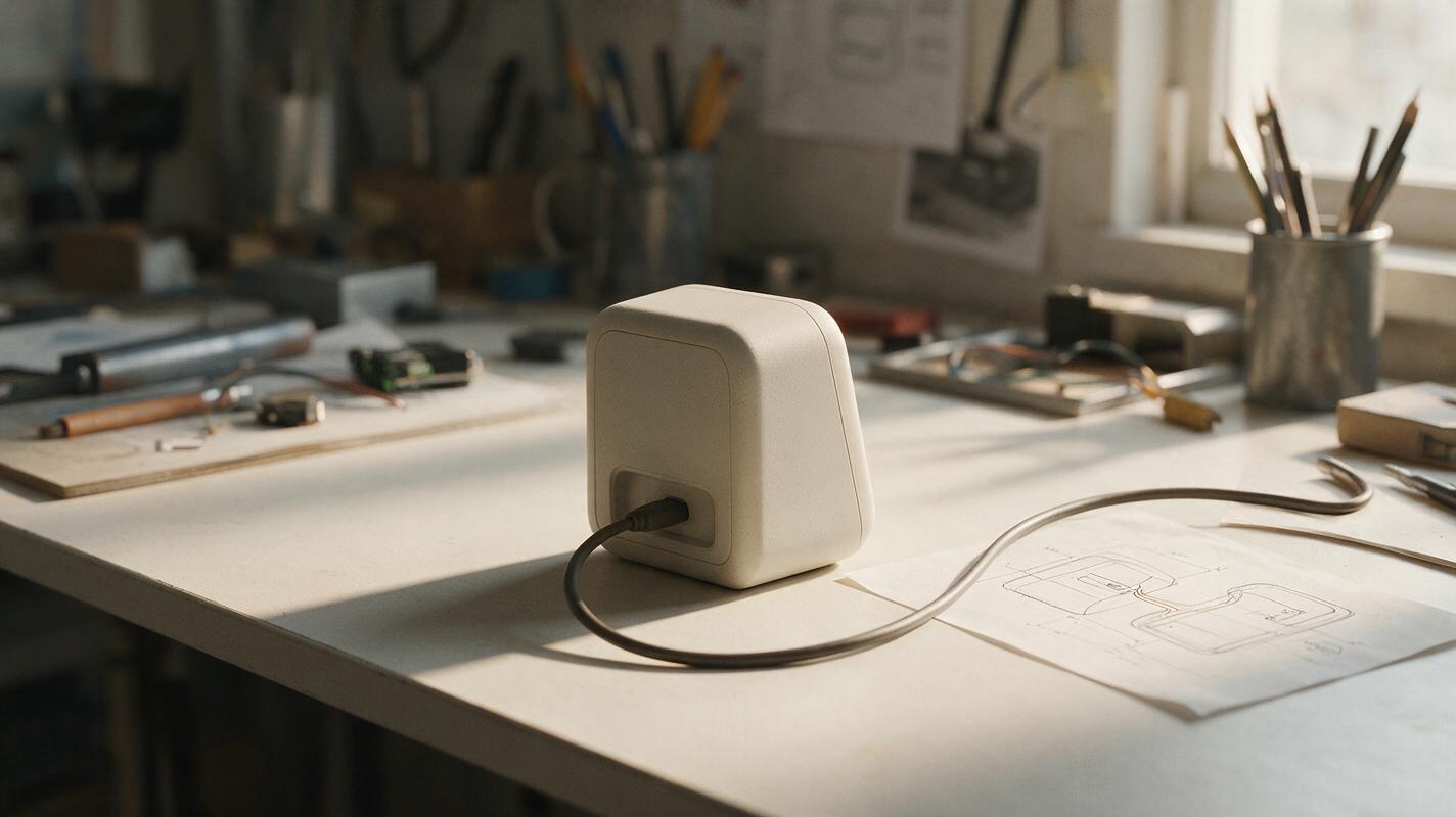
Table of contents
When the cable becomes the design problem
A product render can preserve the housing perfectly and still show a cable emerging from a nonexistent port. For a charger, desk device, or connected prototype, that small error changes how viewers understand the design. The reliable approach is to define the visible connector and cable path before generating the presentation image, then inspect the connection at full size.
This is a visualization workflow, not a substitute for connector packaging, bend-radius calculations, or electrical review. Its purpose is to communicate the connection your team has actually specified.
Why a plausible cable can still be wrong
Image models are good at making a cord look familiar. They are less reliable at respecting a particular product’s port location, insertion direction, and rear geometry. A polished image may contain one of these errors:
- False entry point: the cable disappears into a housing seam instead of the approved port.
- Floating plug: a visible gap or conflicting shadows make the connector look detached.
- Impossible route: the cord crosses a control, passes through the product, or bends sharply at the plug.
- Invented hardware: a new socket, grommet, or strain relief appears because the prompt asked for a cable but did not define its connection.
The fix is not a longer list of generic negative prompts. Give the model a visible, unambiguous route and keep the approved product image as the reference.
Define the port and the intended cable path
Start with an approved product view that actually shows the connection surface. If the rear port is hidden in your hero render, obtain an approved rear three-quarter view or CAD-derived image; do not ask AI to guess what is behind the housing.
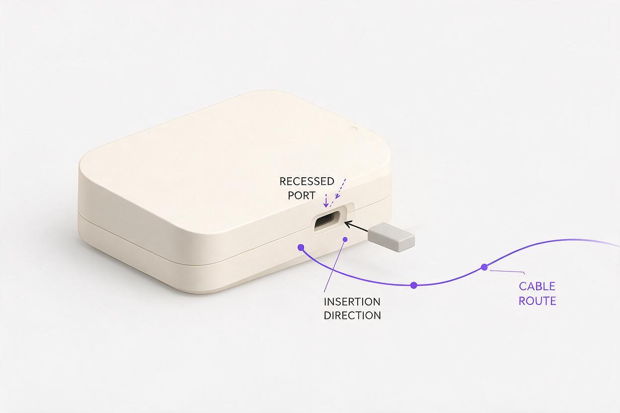
Prepare a simple overlay on a copy of the reference. Mark the port opening, the plug’s insertion direction, a short straight section immediately behind the plug, and two or three points along the intended cable curve. Note which surfaces the cable may pass in front of and where it should leave the frame. The overlay is guidance, not artwork for the final image.
| Reference item | Decision it settles |
|---|---|
| Approved rear or rear three-quarter view | Where the connector can visibly attach |
| Port close-up or CAD crop | Opening shape, orientation, and nearby seams |
| Cable-path overlay | Direction of exit and the intended curve |
| Connector reference, if approved | Which plug form may be depicted |
For example, a desktop sensor might have an approved recessed USB-C port on its rear-right surface. In a rear three-quarter view, the plug should enter that opening, travel briefly away from the housing, then curve toward the right edge of the composition. That is a more useful brief than “add a realistic charging cable.”
Use reference editing instead of a fresh render
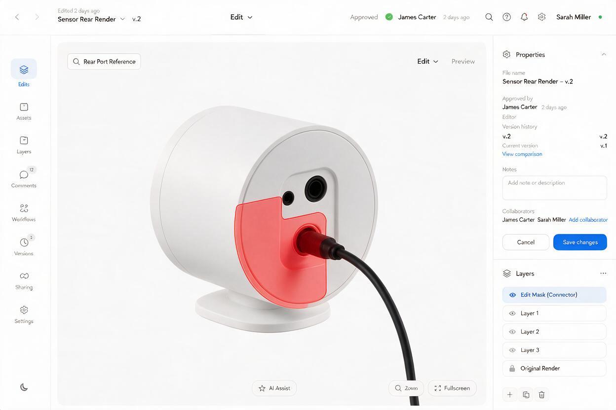
Keep the approved device render as the base image. With nano banana pro, use reference-guided editing if that option is available in your interface; otherwise, generate the cable as a separate visual candidate and composite it onto the approved product image. If masking is available, limit edits to the connector, cable, and their immediate contact shadows. Do not include large areas of the housing in the editable region.
Use a prompt that distinguishes fixed product details from the new element:
Base image: approved rear three-quarter render of a matte off-white desktop sensor.
Preserve the existing product silhouette, rear surface, port opening, seams,
finish, camera angle, lighting, and background.

Add one dark charcoal cable with the approved connector inserted into the
visible recessed rear-right port. The plug aligns with the port opening.
The cable exits straight for a short distance, then makes one broad curve
toward the right edge of the frame. Show a small, consistent contact shadow
at the connection. Keep the controls and product outline unobstructed.

Do not add another port, grommet, screw, label, indicator, or cable.
Do not change the device geometry or depict unseen internal components.
If the model moves the port or redesigns the connector, reject that result rather than describing the mistake away in a presentation caption. A tightly cropped regeneration of the connection area, followed by compositing, is often easier to assess than repeatedly regenerating the whole hero image.
Check the connector before approving the image
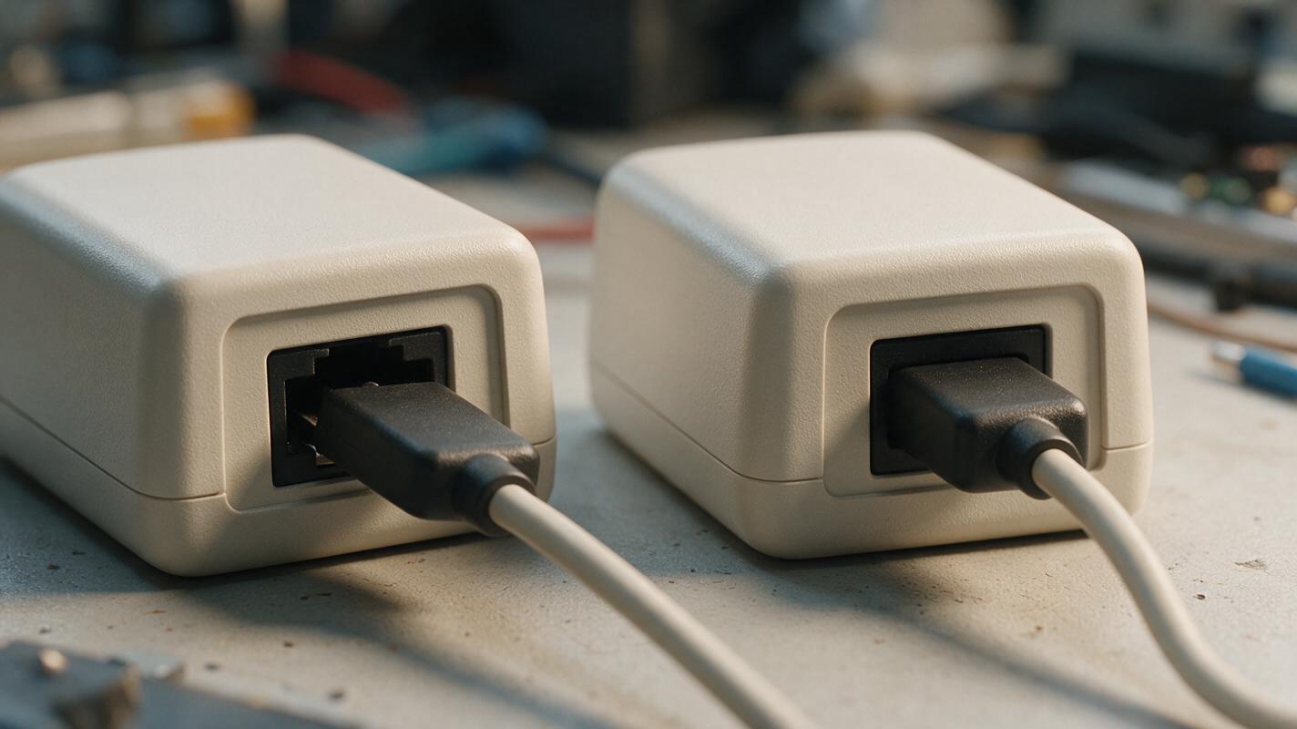
Review the result at both presentation size and a close crop. At presentation size, the cable should support the composition without becoming the focal point. At close range, check whether the plug meets the actual opening, follows its orientation, and casts a shadow consistent with the scene.
- Trace the cable from port to frame edge. Does it remain continuous and stay in front of, rather than pass through, the correct surfaces?
- Compare the housing against the approved base. Have any seams, controls, or port edges moved?
- Inspect the first bend after the plug. Does it read as a gentle route rather than an abrupt kink?
- Look for doubled cables, extra sockets, detached highlights, and shadows that suggest a gap.
A render can show the intended connection clearly without proving that a particular connector, cable, or strain-relief design has been mechanically validated.
If the connection cannot be made legible in the chosen camera view, change to an approved view that shows it. Hiding a questionable plug behind the product only conceals the ambiguity.
Make the final image useful in a design review
Present the finished hero image alongside a small crop of the approved port reference when connection placement is under discussion. Label the image as a concept visualization if the connector specification or cable-routing details are still provisional. This lets reviewers evaluate the intended appearance without mistaking a generated curve for a resolved engineering detail.
Have an approved port view and cable path ready? test this prompt yourself, then compare the connection crop against your reference before sharing the render.
Final checklist
- The source view shows the approved connection surface.
- The plug meets the specified port without inventing hardware.
- The cable follows the planned route and remains visually continuous.
- The product geometry and finish still match the approved render.
- Unresolved engineering details are identified as provisional.
Keywords
ai product design, product rendering ai, cable placement, product visualization, hardware concept render, reference-based editing, nano banana pro