AI Product Renders From Multiple Angles Without Inventing the Back
A polished front view does not give an image model enough information to design a product’s rear or underside. This guide shows product designers how to build a reference-led multi-view presentation, identify unsupported details, and check whether the resulting images still depict one design.
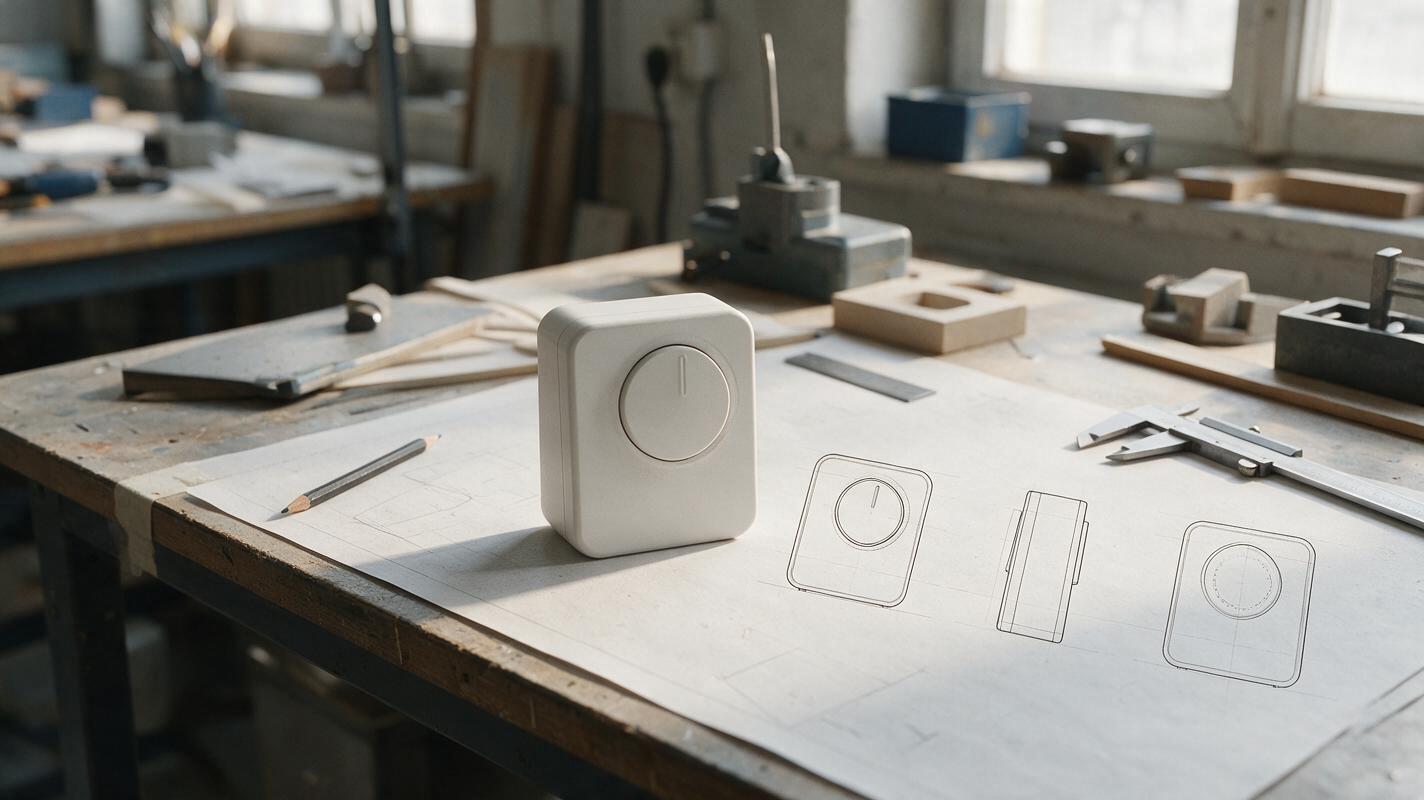
Table of contents
One product, several views—not several different products
A convincing front render is easy to mistake for a complete product definition. Ask for a rear three-quarter view, though, and an image model may invent a battery door, move a seam, or change the depth of the housing. The result looks like a coordinated presentation until someone compares the views side by side.
For a design review, the goal is not simply to generate more camera angles. It is to show only the geometry you can support, keep shared features consistent, and make unresolved surfaces visibly provisional. A reference-guided ai image generator such as Nano Banana Pro can help develop presentation images, but the reference package—not the prompt alone—must define the product.
Decide what each view is allowed to reveal
Before generating anything, separate the design into three categories: defined surfaces supported by drawings or CAD, partly defined surfaces whose overall shape is known but whose details are not, and undefined surfaces that have no approved source. This prevents a request for a camera angle from becoming an accidental design decision.
Consider a hypothetical desk timer with an off-center circular dial and a rectangular display. A front sketch establishes their placement, but it cannot establish the rear seam or underside feet. If you have only that sketch, a front view and a shallow front three-quarter view may be defensible. A detailed rear view is not.
| Available reference | Reasonable presentation view | Risk to avoid |
|---|---|---|
| Front sketch only | Front and shallow front three-quarter | Revealing an invented back |
| Front plus side drawings | Front, side, and restrained three-quarter | Changing thickness between views |
| Front, side, rear, and top CAD views | A fuller multi-view concept board | Treating rendered details as engineering-verified |
If a surface matters to the review but has no source, resolve it in the design file first—or label the image as an exploratory proposal rather than an approved view.
Lock the views to an actual source
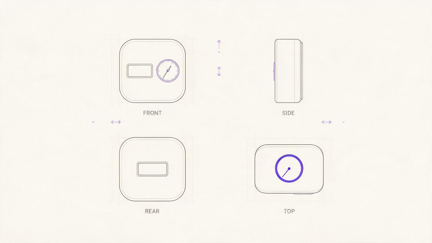
Build a compact reference sheet rather than uploading an assortment of unrelated images. Export front, side, rear, and top views from the same CAD revision when those views exist. Keep a shared centerline, consistent proportions, and clear indications of which features wrap around an edge. If your sources are sketches, mark dimensions and alignments that must not drift; do not present a sketch as a measured orthographic drawing.
For the desk timer, the reference sheet might fix the dial’s offset from the housing centerline, the display’s width relative to the dial, overall thickness, corner radius, and the location of a rear seam shown in CAD. Include a neutral material reference separately so the model does not infer geometry from reflections in a glossy example photo.
Give each view a purpose. A front view communicates interface layout; a side view communicates thickness and taper; a rear view shows only rear features established by its source. Generate those views individually before arranging a board. A single prompt requesting four images in one frame can produce an attractive layout while hiding contradictions between the depicted objects.
Reference-led prompt for an approved side view
Use the supplied front and side views of the same desk timer concept as design references. Create one clean side-view product presentation render against a neutral studio background. Match the side-view silhouette, overall thickness, front-to-back taper, and corner transitions shown in the source. Keep the front-facing dial and display consistent with the front reference wherever they are visible. Do not add buttons, ports, seams, feet, text, or openings that are not shown in the supplied views. Use soft lighting that makes the housing profile easy to inspect. This is a visual concept render, not a manufacturing drawing.Replace the example’s named features with your own approved feature list. If a model still adds unsupported details, remove those details through a focused edit or use a more tightly controlled view. Repeating “do not invent anything” cannot supply missing geometry.
Match cameras and lighting before comparing details
Even accurate-looking images can imply different designs when one uses a wide lens and another uses a compressed, nearly orthographic view. Choose a consistent presentation convention: matched orthographic views for form inspection, or restrained three-quarter views for a concept board. Avoid asking the model to rotate an existing beauty shot through a large angle when the newly exposed surfaces are not documented.
Hold finish and lighting direction reasonably steady across the set. Otherwise, a highlight may make the sidewall look thicker in one frame or conceal a seam in another. Place the finished views at comparable scale, then align them on a shared baseline. This makes deviations easier to see than a collage of differently sized hero shots.
For a three-quarter image, describe the camera’s limits as well as its position:
Create a front-right three-quarter presentation view of the supplied desk timer concept. Keep the camera close to the front so the image reveals the approved right-side profile but does not expose the undocumented rear face. Preserve the off-center dial, rectangular display, housing outline, and approved material boundaries from the references. Use a neutral background, soft studio light, and a modest perspective. Do not add decorative controls or imply access to surfaces absent from the supplied references.Spot geometry drift before a design review
Inspect the renders as a set, not as isolated images. Compare features that appear in two or more views: the dial’s relationship to the display, the corner transitions, the thickness at the front edge, and where material boundaries meet the sidewall. A strong render can still fail this test.
- Silhouette check: Does the side profile agree with the source, including taper and radii?
- Feature check: Are shared controls the same size and in the same relative positions?
- Edge check: Do visible seams and material breaks continue plausibly across adjacent views?
- Visibility check: Has a newly visible face acquired unsupported detail?
- Status check: Can a reviewer tell which images represent approved geometry and which are exploratory?
If one image fails, correct that view against the source. Do not silently modify all the other views to match the model’s invention. For a particularly important contour, overlay a low-opacity CAD export or drawing on the render and compare landmarks. That check is more reliable than judging each image from memory.
Present uncertainty instead of hiding it
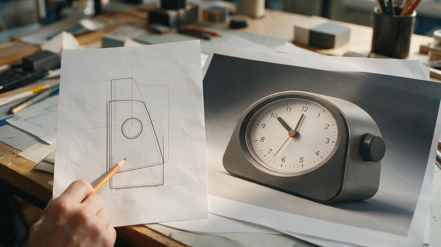
A multi-view board does not need to show every surface. Cropping, a shallow camera angle, or a separate neutral line drawing can communicate an unfinished concept more honestly than a fabricated rear hero render. If the team wants to explore rear treatments, present them as distinct alternatives, not as additional views of a supposedly fixed design.
Keep source drawings and final images together when handing off the board. Label the render as concept visualization, and leave dimensions, clearances, assembly decisions, and performance claims to the appropriate design and engineering work. The image is useful because it makes an established direction easier to discuss—not because it proves the object can be manufactured as pictured.
Final checklist
- Every visible product surface has a source, or its exploratory status is explicit.
- Shared features retain their position, proportion, and appearance across views.
- Camera choices reveal approved geometry rather than forcing an invented rear.
- Unsupported ports, seams, feet, and controls have been removed.
- The final board distinguishes visual presentation from engineering documentation.
Have a front and side reference ready? test this prompt yourself with those views first, then add new angles only when your source material supports them.
Keywords
ai product renders, multi-view product rendering, industrial design ai, product visualization, reference-guided rendering, nano banana pro, concept design ai